With the continuous improvement of the quality requirements of yarns in the market, the requirements of the textile mill equipment are getting higher and higher. The requirement for the draw frame is to install a short-segment autoleveling device. Because of the cooperation of the draw frame, the long-segment weight shift and the short-segment periodic quality fluctuation cannot be solved, and the draw frame produces uneven drafting on the sliver. After the autoleveling device is installed, the unevenness of the feeding sliver can be automatically and effectively detected, and the on-line detection can be performed, and the drafting ratio can be adjusted online to control the quality of the output sliver. Therefore, it can be seen that the addition of an autoleveling device to the draw frame is of great significance for controlling the quality of the yarn, and is also an inevitable trend in the development of the draw frame. The HY31 draw frame is the key bidding project of our company in 2003. The machine is a single-eye high-speed draw frame with a maximum delivery speed of 1000m/min. In order to meet the needs of the market and improve the quality of yarn, we selected the BYD-III short-segment autoleveling device developed by the Sixth and Third Research Institute of China Aviation Industry Corporation.
The BYD-III autoleveling device is an open-loop short-segment autoleveling device suitable for high-speed draw frames. It can accurately detect short clips fed into the sliver through an efficient control system and a high-performance microcomputer system. Unevenness, rapid smoothing of the sliver count deviation by using a fast-responding all-digital AC servo system. It adopts the leveling method of fixed length detection and fixed length control to control the draw frame. It can detect and control the fragments of the length of the feed sliver which are as short as 1mm or longer. It has perfect system self-test function and sliver online. The detection function can display multiple processes, quality, output and other data online, and can issue alarms according to the quality limit set by the user and automatically stop.
Figure 1 shows the composition and leveling principle of the BYD-III autoleveling device. According to the tasks of each component in the system, the system can be divided into three parts, namely: detection system, control system and actuator. . The working process of the device is as follows: after the fed sliver is pressed by the concave and convex measuring member, the thickness signal can represent the linear density signal, and the convex roller in the concave and convex roller changes with the thickness of the compressed sliver after compression. When the movement occurs, the displacement sensor converts the displacement signal representing the change in the density of the sliver into an electrical signal and sends it to the computer. The computer compares the signal with the set standard value, calculates the difference, and stores it. When the feeding sliver corresponding to the signal reaches the fiber shifting point of the main drafting zone, the control system sends a signal to change the rotational speed of the servo motor, thereby changing the rotational speed of the middle roller, thereby changing the main drafting multiple of the draw frame, Correct the deviation of the feeding sliver to make the feeding sliver even.
After the drafting is completed, the output sliver is measured by the strip sensor at the striping point, and the computer calculates the index based on the measured data and displays it on the liquid crystal display.
Detection Systems
The detection system of the BYD-III autoleveling device includes three parts: the strip detection, the strip detection, and the speed detection. Since the weight deviation of the feeding sliver is adjusted during the control of the entire leveling system, the accuracy of the feeding sliver detection is critical to the overall system. The mechanism is located at the back of the machine feeding tampon, including the concave and convex roller detection mechanism and the input detection displacement sensor with a measurement accuracy of 0.1% or more. The working principle is that the concave roller is fixed, and the convex roller is pressed against the concave roller by pneumatic pressing to form a measuring jaw. Due to the change of the thickness of the input sliver in the jaw, the position of the convex roller changes accordingly. The displacement of the convex roller is transmitted to the displacement sensor by a set of linkage mechanism, so that the displacement sensor generates a voltage signal related to the thickness of the sliver. The cross-sectional area actually detected by the mechanism is the product of the groove width of the concave roller and the detected thickness. The groove width of the concave roller is constant. The change is only the thickness of the sliver. It must have a good line density with the feeding sliver. Linear relationship. Therefore, it is necessary to select different specifications of the bump roller and the pressing pressure according to different raw materials, varieties, and feed amounts. At the same time, it is necessary to install relevant parts and electrical components in strict accordance with the requirements, eliminate human factors and improve measurement accuracy. The advantage of this mechanism is that the measurement is stable and reliable, is not susceptible to external interference, and is easy to operate and use. The strip detection mechanism is located above the coil plate and includes a step roller and a displacement sensor. The working principle is similar to the entry detection. The difference is that the step roller is pressed by the spring instead of pneumatically pressurized. The mechanism can directly measure the quality of the output sliver and display the measured results on the screen, including the Uster strip CV% value of the sliver, the weight deviation of the 5 m segment sliver A%, and the 5 m segment cotton. The weight unevenness rate of the strip is H% and the quality index such as the spectrogram. This is important for system commissioning and quality monitoring. The speed detection includes a speed measuring gear and a speed measuring sensor with a response frequency greater than 10KHz. There are three sets of the whole machine, one set is installed on the transmission chain under the concave roller, and is used for detecting the feeding speed, and one set is mounted on the shaft of the output pressing roller. It is used to detect the production speed of the draw frame, and the other is installed on the drive shaft between the main motor and the differential gear box to detect the fixed speed of the input differential gear box.
Control System
The control system is the core part of the entire leveling system, in which the A/D board and the CPU board are the main components for the leveling operation. The system has powerful data processing functions and good real-time performance. The signals of all the sensors directly enter the control system, wherein the voltage signal outputted by the displacement sensor enters the A/D converter, and the voltage signal of the displacement amount is converted into a digital signal by A/D for processing. The signal of the speed sensor is a pulse signal and goes directly to the control unit. The signal connection between the control unit and the outside world is realized by the KZ module, and the control signals for the servo system are output through the KF and DJ modules. Thereby controlling the rotational speed of the servo motor.
Executive agency
The mechanism consists of a differential gearbox, servo motor and servo controller. As can be seen from Fig. 1, the speed of the input differential gearbox is constant, and the rotational speed of the servo motor is varied, so that the output speed of the differential gearbox changes, thereby changing the transmission mechanism of the rear roller. The rotational speed also changes the drafting ratio of the main drafting zone. In order to achieve the purpose of smoothing the sliver. Important here are the parameters such as accuracy, response time, and dynamic characteristics of the servo system. The requirements for the servo system are: low inertia, large torque, maintenance-free, fast response, etc. This device selects the AC servo system of SANYO Company of Japan, which has high precision, fast response and good dynamic performance. Meet the requirements of the system.
With the continuous improvement of modern spinning production technology, the application of the self-leveling technology of the draw frame is very important, and its technology and function have become the key to the modernization of the drawing process. After the BYD-III autoleveling device is installed, the draw frame has a good leveling effect on the short segments of the sliver. The Uster strip should be better than the non-leveling state, and the yarn quality is improved. However, since the HY31 draw frame of our company has just been installed and is being commissioned, the actual effect of the device will be further verified after the cotton spinning test.
Higher quality and Lower Price Steel Plate Flange Produced by Jimeng Group.
Size:DN 10-DN 2000
Standard:ANSI,ASME,JIS,KS,GOST,DIN,UNI,EN,GB
Export Country:US.UK.SERBIA,RUSSIA,ITALY,IRAN,KOREA,JAPAN,SPAIN,CHILE,BRAZIL
Pressure:5k,10k,16k,20k,class150,class 300,class600,class900,PN0.6,PN1.0,PN1.6,PN2.5
Type:PL,SO,WN,SW,TH,BL
Sealing Surface:FF,RF,RJ,FM,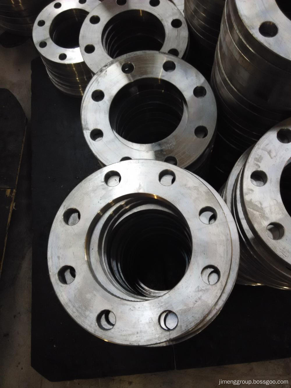
Steel Plate Flange
Steel Plate Flange, Slip On Plate Flange, Carbon Steel Plate Flange
Hebei Jimeng Highstrength Flange-tubes Group Co.,Ltd. , http://www.jimengflange.com