First, technical indicators
Processing smoke volume: ≈120000 Nm3
Export SO2 emission concentration ≤ 35 mg/Nm3
Export dust emission concentration ≤5 mg/Nm3
Desulfurization guarantee efficiency ≥98%
Desulfurization system Ca/S ≤ 1.03 mol/mol
Flue gas pressure drop through desulfurization system ≤1200 Pa
Desulfurization system equipment availability is not less than 95 %
Second, the process requirements
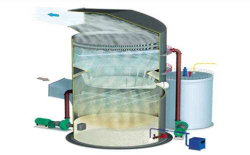
After the boiler flue gas is dusted by the dust collector, it enters the spray tower through the induced draft fan. The flue gas first enters the pre-spray stage of the spray tower. The temperature of the flue gas is reduced to the temperature favoring the chemical reaction through the pre-spray device (complete the initial absorption and capture of the primary flue gas desulfurization), and the flue gas is evenly distributed. In the desulfurization tower, the upward flue gas flow is in reverse contact with the downward mist-like slurry, and the deep purification of the flue gas (ie, the second absorption and capture of the flue gas's deep desulfurization) is performed; the water is removed by the demister, and then cleaned The smoke is discharged into the atmosphere through the chimney.
The lime slurry is made by mixing lime powder and process water. The fresh lime slurry made by the lime slurry preparation system is sent to the spray tower through the slurry supply pump and mixed with the gypsum slurry in the spray tower. The slurry is sent to the spraying device through a circulation pump and atomized by the nozzle to form gas-liquid mass in the tower with contaminants in the flue gas.
The absorption liquid pool in the spray tower is divided into a reaction zone and an oxidation zone. The main reaction zone is the vapor phase transfer of SO2. The oxidation zone mainly oxidizes the sub-salts. The oxidation fan is responsible for providing oxygen to the oxidation zone, and the pulse pump is mainly agitating the slurry to avoid precipitation of the byproducts of the desulfurization. When the density of the slurry reaches a certain value, the slurry is discharged from the slurry discharge pump and enters the byproduct processing system. The by-product processing system mainly includes a cyclone separator and a vacuum belt conveyor. Mud pump and frame filter press.
The purified flue gas stream is defogged by a demister, where the mist carried in the flue gas is removed, while the demister is flushed with process water according to a specific procedure. The demister flushing has two purposes: first, to prevent the demister from plugging; second, flushing water is also used as replenishing water to stabilize the absorption tower liquid level.
The temperature of the flue gas at the exit of the spray tower is generally about 55°C, which is saturated smoke.
Third, the system requirements
The desulfurization and dust removal process system mainly includes the following subsystems:
Smoke system
Slurry preparation system
Absorption system
Byproduct processing system
1. Flue gas system
The main equipment includes baffle doors, flue ducts, etc.
(1) flapper door
The bypass flapper door of this project is intended to use double seal flapper doors, while other flapper gates use single-layer flapper doors.
(2) Flue system
An expansion joint is installed at the necessary position of the flue to meet the displacement caused by compensating the thermal expansion of the flue. Expansion joints should absorb axial and radial displacements of all connected equipment and flue ducts under all operating and accident conditions.
2. Slurry preparation system
The desulfurization process uses lime as a desulfurizing absorbent. Outsourcing lime material,
The main function of the lime slurry preparation system is to prepare a qualified absorbent slurry and provide it with a sufficient amount according to the needs of the absorption tower system to achieve the desired desulfurization efficiency.
The powder material stored in the silo enters the slurry tank through the plug valve and the star feeder at the bottom of the silo, and is made into a slurry by mixing the lime powder with the process water through the action of the pulp tank mixer. The prepared slurry was driven into the spray tower via a slurry feed pump.
The lime slurry preparation system has the following major equipment, but is not limited thereto:
(1) lime storage
(2) Beating device
(3) bag filter
(4) manual plug valve
(5) Star Feeder
(6) Pulping tanks
(7) Pulping tank mixer
(8) Slurry supply pump
3, absorption system
The absorption system is a furnace and a tower. One tower double loop design. After pre-spraying and spraying the flue gas flows through the demister, the small droplets entrained in the flue gas slowly condense into relatively large droplets, then return to the slurry zone through the demister, and the clean flue gas From the top, the chimneys are discharged into the atmosphere. The flue gas left the demister to carry a water drop content of ≤75 mg/Nm3.
In order to supplement the moisture lost due to the cooling of the hot flue gas and the loss of gypsum crystals, the tower level is usually controlled by demister flushing water. The density of the slurry in the tower is controlled by adjusting the discharge of the gypsum slurry in the spray tower. The pH in the slurry tank is controlled by the amount of fresh lime slurry added.
(1) Double loop technical features
a.Applicable to sulfur-containing coal or FGD systems with high desulfurization efficiency;
b. The first cycle pH is controlled between 4.5 and 5.3, which is conducive to the dissolution of limestone and the crystallization of gypsum, and can obtain high quality gypsum;
c. The secondary circulation PH value is controlled between 5.8 and 6.4, which can get higher desulfurization efficiency, reduce the liquid-gas ratio, and reduce energy consumption;
d. After the pretreatment of the flue gas in the first cycle, the content of dust, HCL and HF is reduced, which is conducive to high desulfurization efficiency in the secondary cycle;
e. Independent control of each cycle, easy to optimize and rapid adjustment, can adapt to large changes in sulfur content and load.
f. Independent primary and secondary circulating pools can reduce accidents
g. Cone-shaped collection bowl can distribute smoke flow field uniformly to improve the demister mist removal effect.
(2) Spray Tower
a. Structure
The spray tower is a circular tower with a diameter of 4m.
b. Material
The spray tower uses carbon steel-lined glass flakes.
(3) spray layer and nozzle
a. Structure
The spray layer is designed in the middle of the spray tower, which also facilitates the overhaul and maintenance of the nozzle.
b. Material
Spray system piping: FRP.
Nozzle: Silicon Carbide (SiC) is a brittle material, but it is particularly wear-resistant and has excellent chemical resistance. It can run for a long period of time without corrosion, without scaling and blockage of plaster.
(4) Demister
a.Function and structure
The demister is used to separate the droplets carried by the flue gas. The demister is in the form of a baffle plate.
b. Selection
Mist eliminator form: FRP, 2-stage baffle plate
Rinse pipe: PP
Rinse nozzle: PP
(5) Slurry Circulation Pump
a. Structure
Slurry circulation pump adopts unit system configuration. Each furnace is equipped with a circulating pump. Each circulating pump corresponds to a spraying device in a buffer chamber, and a standby circulation pump is provided.
b. Selection
The medium of the material that can be fully adapted to the transport is selected and adapted to a Cl-concentration of up to 30 g/l. The pump body adopts carbon steel skeleton and modified polyethylene.
(6) Oxidation fan and oxidation duct
a. Function and structure
The function of the oxidation fan is to provide sufficient oxygenated air for the slurry in the spray tower slurry pool. The soundproof hood is installed outside the fan; the amount of oxidizing air is supplied according to the maximum output of the operating fan, no regulator is provided, and the spray tower is provided with an inlet for oxidizing air. Through the oxidizing air duct, a uniform and tiny air bubble is generated, the air volume and the air bubbles in the cross section of the slurry pool are well dispersed, the contact surface between the air and the slurry is increased, the oxidation effect is good, the utilization rate of the oxidation air is high, and the amount of oxidation air is small And guarantee the quality of gypsum.
b. Selection
The oxidation fan casing is made of grey cast iron; the impeller is made of ductile iron; the main and secondary shafts are made of carbon steel; the helical gears are made of alloy steel; and the bearings are made of rolling bearings.
(7) Liquid-solid separation system
When the system slurry reaches a certain pH and density, the cyclone will send the gypsum slurry into a vacuum belt conveyor. The vacuum belt conveyor discharges the filtrate of the gypsum slurry into the self-flowing spray tower; solids such as gypsum are regularly transported from the car.
The solid-liquid separation system mainly includes the following components:
a. Cyclone separator
b. Vacuum belt conveyor
c. Discharge pump
d. Plate and frame filter press
(8) Auxiliary system
a. Comprehensive building
The second floor of the complex is used for desulfurization of byproducts, distribution room, desulfurization and denitrification control room.
b. Process water system
The process water is used for mist eliminator cleaning (high-pressure water) of the spray tower, flushing water and cooling water for the cleaning line of the buffer tank.
Process water system configuration process tanks, process pumps, demister flushing pumps, etc.
The process tank is used to store the industrial water supplied by the plant and buffer the system water supply. The amount of water stored in the process tank ensures that the desulfurization and dust removal system can consume 4 hours of water.
c. Compressed air system
The compressed air of this solution is to provide various instruments and valves in the system.
Fourth, electronic control system
The electronic control system uses DCS to complete the control and signal acquisition. The entire control system can realize automatic control, with alarm, pressure relief protection, motor protection and other functions, and has sufficient expansion capabilities.
The entire system can be switched between manual and automatic. In the very operating state, the equipment, fans, pumps, and control valves can be manually operated in the field.
The integration of electrical instrumentation control, electrical equipment and process control is accomplished by a control system, which improves the integrity and reliability of the system, and has the function of interlocking pumps. All motors are equipped with control boxes in situ.
The liquid level of the pool is displayed by the microcomputer and linked with the relevant equipment. The pumps in the pump room are displayed by the microcomputer. The control of the damper opening, the concentration of the desulfurizing agent, regeneration, slurry concentration, and dewatering can be automatically controlled. Can be controlled on the control panel start and stop, and there is a local start and stop button.
All electrical control systems use centralized control. On-site transactions require the supplier to design, monitor, and centralize pump rooms.
Source: Yancheng Tiancheng Environmental Protection Equipment Co., Ltd.
The main sources are mechanical impurities that remain in the hydraulic system after cleaning, such as rust, cast sand, welding slag, iron filings, paint and cotton yarn, etc. External impurities entering the hydraulic system, such as through the oil filler entrance and dust entering at the scraper seal. Impurities generated during the working process, such as debris formed by the hydraulic action of the seal, metal powder generated by relative wear and movement, colloid, asphaltene, carbon residue, etc. Due to oxidative deterioration of the oil.
Hydraulic Filter,Hydraulic Filtration,Hydraulic Turbine Filter,Hydraulic System Filter
Xinxiang Shengda Filtration Technique Co., Ltd. , https://www.shengdafiltration.com