1 Introduction Ultrasonic sensors are widely used due to their high measurement accuracy, fast response, and low price. The traditional application is that one transmitter head corresponds to one receiver head, and multiple transmitter heads correspond to one receiver head. However, we found in practical applications that if the surface of the obstacle is large (such as a wall), the ultrasonic sensor can be used to accurately measure the distance, but if it is used in a collision avoidance system of a car, the obstacle is in a column shape and the ultrasonic wave is emitted. The head has a certain scattering angle (left and right), so even if the obstacle is not in front of the car, the ultrasonic wave can still detect the oblique frontal echo, which is difficult and misleading to intelligently control the movement of the vehicle. In order to solve this problem, we propose A scheme using dual receivers and a set of specific control strategies from a practical point of view.
2 System Structure Flow Design Our entire system needs to complete functions such as distance measurement, speed measurement, positioning, and control of car movement. The system includes the following six parts: ultrasonic transmission circuit, ultrasonic receiving circuit, signal processor, temperature measurement, car control circuit, etc. Five parts. System structure diagram shown in Figure 1: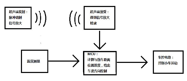
Figure 1: System block diagram A 40k square wave is generated by a single-chip microcomputer, and after being amplified, an ultrasonic sensor transmitter head is driven to emit an ultrasonic wave. After being reflected by an object in front, it is captured by the receiver. After the calculation of the capture time of the two receivers and temperature compensation is added, the final front is determined. The direction and distance of the car, and then through the previous data difference to calculate the relative speed of the previous car, and finally through the speed, distance and position of the three data for intelligent control, control the car turning or slow down.
The specific hardware consists of: MCU adopts AT89S52 single-chip microcomputer, P1.0 port outputs 40K square wave signal required by ultrasonic transducer, drives the sensor after inverter 7404, in order to enable the ultrasonic wave to launch farther, we pick up The three transmitters use external interrupt 0 to monitor the return signal output from the ultrasonic receiver circuit. The echo detection uses infrared detection integrated chip CX20106. The display circuit uses a simple 4-bit common-yang LED digital tube, and the code is 74LS244 for bit-code. 8550 driver. The temperature measurement section uses 18B20 to measure the current ambient temperature to determine the speed of ultrasonic propagation.
3 MCU algorithm control 3.1 distance calculation and position judgment SCM can calculate the time between transmitting and receiving ultrasonic, according to the actual temperature measurement system to find out the sound speed at the corresponding temperature, calculate the reflector distance from the two receivers distance. Theoretically, the spatial position of the object can be derived directly from the above two data (as shown in Figure 2 and Formulas 1 and 2).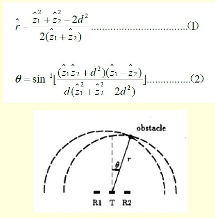
Figure 2 Spatial orientation of ultrasonic sensors Where d is the distance between R1 and R2, and z1 and z2 are the distances from the object to each receiving end. If the calculation is made directly, it will be too complicated. If an ordinary single-chip processor takes more time, then we propose a distance calculation based on the distance between them. Poorly determine the location of the object. Generally speaking, the car only cares about the object in front of the car. We set a distance parameter l to represent the horizontal distance between the front obstacle and the car, and then set a distance parameter h, which represents the vertical distance between the front obstacle and the car. We can derive the relationship between h, l, d and z2-z1 from the following relationship (Equation 3---Equation 6). 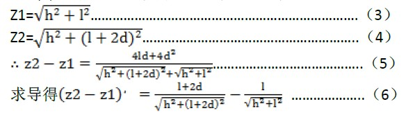 It is not difficult to find that the first term is always greater than the second term, so z2-z1 is an increasing function of l, and as z decreases, z2-z1 also becomes larger. That is to say when the obstacle is close to the car, if it deviates from the center of the car (that is, it will not hit), there is a clear feature that the value of z2-z1 will be relatively large, we can take d=5cmh=30cm, let l In the [10cm, 30cm] change, the curve made as shown in Figure 3, the physical relationship between the various physical quantities shown in Figure 4.
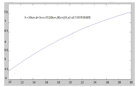
Figure 3z2-z1 and l relationship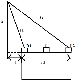
Figure 4 The geometric relationship of each physical quantity It is not difficult to find that when the distance is in the interval of [10cm, 30cm] (h<30cm), the difference of z2-z1 will be >4cm. According to this, we set a threshold value of 4cm, when the difference is detected to be greater than 4cm, no need By doing any brake control and directly passing straight through, through such a simple calculation, we can effectively avoid that the value of z1 and z2 caused by the obstacle that deviated from the center of the trolley is too close to the trolley, which leads to possible brake misjudgment. In doing this project, we use a modeless car model, so the design threshold is not very large, if you apply to the actual car model can change the size of the threshold according to the situation.
3.2 Speed ​​Calculation Speed ​​We use a simple approximation to estimate the distance. We can calculate the distance between the system's ranging distances to be about 120 ms. By comparing the current ranging result with the previous ranging result, we can estimate according to formula 7 Approximate current speed:
3.3 System Flow (see Figure 5).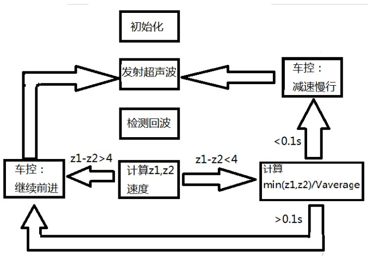
Figure 5 system flow 4 part of the test results Table 1 is our single test results for the distance measurement circuit: (in cm).
Table 1 Ranging results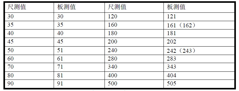
From this table we can see that our ranging circuit is very accurate.
Figure 6 shows our test results for the dual head solution: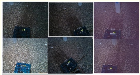
Figure 6 dual receiver head test results Of these six figures, the top three are the distances calculated with the right receiver receiving signal time, and the next three are the distances calculated with the left receiver head receiving signal time. It can also be seen that when the obstacle is deviated At the center, the distance measured by the left and right receiving heads is significantly different, and thus can be used for positioning.
Finally, after we completed the debugging of the entire car system, we used it to test and found that whether it is a moving or stationary obstacle, the car can accurately judge whether to move forward or stop at any position in front of the car.
5 conclusions In summary, this system proposes an on-vehicle automatic speed measurement and ranging control system based on dual ultrasonic receivers and 3 transmitters, which can effectively play a role of pre-judgment for driver protection, etc. When the driver is driving When an emergency control measures are taken in case of an emergency, the system can also be forced to correct or alert the driver to check. Because the system is simple, economical and stable, it has a very large market prospect.

2 System Structure Flow Design Our entire system needs to complete functions such as distance measurement, speed measurement, positioning, and control of car movement. The system includes the following six parts: ultrasonic transmission circuit, ultrasonic receiving circuit, signal processor, temperature measurement, car control circuit, etc. Five parts. System structure diagram shown in Figure 1:
Figure 1: System block diagram
The specific hardware consists of: MCU adopts AT89S52 single-chip microcomputer, P1.0 port outputs 40K square wave signal required by ultrasonic transducer, drives the sensor after inverter 7404, in order to enable the ultrasonic wave to launch farther, we pick up The three transmitters use external interrupt 0 to monitor the return signal output from the ultrasonic receiver circuit. The echo detection uses infrared detection integrated chip CX20106. The display circuit uses a simple 4-bit common-yang LED digital tube, and the code is 74LS244 for bit-code. 8550 driver. The temperature measurement section uses 18B20 to measure the current ambient temperature to determine the speed of ultrasonic propagation.
3 MCU algorithm control 3.1 distance calculation and position judgment SCM can calculate the time between transmitting and receiving ultrasonic, according to the actual temperature measurement system to find out the sound speed at the corresponding temperature, calculate the reflector distance from the two receivers distance. Theoretically, the spatial position of the object can be derived directly from the above two data (as shown in Figure 2 and Formulas 1 and 2).
Figure 2 Spatial orientation of ultrasonic sensors
Figure 3z2-z1 and l relationship
Figure 4 The geometric relationship of each physical quantity
3.2 Speed ​​Calculation Speed ​​We use a simple approximation to estimate the distance. We can calculate the distance between the system's ranging distances to be about 120 ms. By comparing the current ranging result with the previous ranging result, we can estimate according to formula 7 Approximate current speed:
3.3 System Flow (see Figure 5).
Figure 5 system flow
Table 1 Ranging results
From this table we can see that our ranging circuit is very accurate.
Figure 6 shows our test results for the dual head solution:
Figure 6 dual receiver head test results
Finally, after we completed the debugging of the entire car system, we used it to test and found that whether it is a moving or stationary obstacle, the car can accurately judge whether to move forward or stop at any position in front of the car.
5 conclusions In summary, this system proposes an on-vehicle automatic speed measurement and ranging control system based on dual ultrasonic receivers and 3 transmitters, which can effectively play a role of pre-judgment for driver protection, etc. When the driver is driving When an emergency control measures are taken in case of an emergency, the system can also be forced to correct or alert the driver to check. Because the system is simple, economical and stable, it has a very large market prospect.
Machining is a form of subtractive manufacturing utilizing sharp tools to physically remove material
to achieve a desired geometry.Our custom CNC machining is carried out by automatic screw machines,
CNC turning machines, and CNC machining centers.
We supply two categories of CNC machined parts:
(1) Parts machined from formed materials such as rod, sheet, and block.
(2) Parts machined after casting, forging, stamping, (metal) injection molding, and powered metals.

Machining Parts,Cnc Precision Parts,Cnc Milling Parts,Cnc Machining Part
Hebei Mingda International Trading Co.,Ltd , http://www.mingdacasting.com