As a meteorological instrument, small weather stations are generally placed in open environments such as the field, so that we can more accurately measure the meteorological data. Sometimes we need to specifically detect night-time data, or we can specialize in statistics of daytime data if we Opening and closing small weather stations every day will increase the workload and will also waste a lot of manpower and material resources. Since there are not only only one small weather station, the light control function is born under such circumstances. , The following will introduce to you the realization of the principle of liquid crystal light control in small weather stations.
Optical switch devices in small weather stations are important devices in optical communication networks. Their main function is to switch the channels of the network to realize optical signal exchange or network self-healing protection. The requirements for optical switches are low insertion loss, low crosstalk, fast switching speed, low switching power consumption, good repeatability, long life, compact structure, and easy operation. Currently practical optical switching devices mostly use mechanical control methods. These devices have the following major drawbacks: First, the response speed is slow, generally difficult to faster than 10ms; Second, the larger size, is not conducive to system integration; Third, the limited life of moving parts.
The small-scale meteorological station's liquid crystal switch technology has great advantages with its low switching energy, fast response, good reliability, and no moving mechanical structure. In addition, the liquid crystal material has a low absorption loss in the infrared band, and thus can be applied to the C and L bands. The advantages of using liquid crystal modulators for optical switching have been described. The liquid crystal modulator has no moving mechanical structure and it operates a polarization to route optical signals to such a solid state device. The liquid crystal cells require low control voltages and currents, and therefore, they consume low power relative to mechanical optical switches. The liquid crystal switch already has 1×2, 1×8, 2×2 upper/lower and 8×8 upper/lower switches. These switches have lower insertion loss, polarization-dependent loss, and temperature-dependent loss than some other solid state (without mechanical movement) switches and have low polarization mode dispersion and wide operating spectral range. Compared with mechanical optical switches, it has faster switching speed and smaller size.
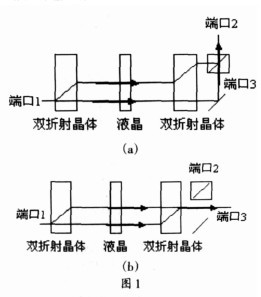
The working principle of the polarization beam splitting liquid crystal light switch of the small weather station first divides the input light into two polarized lights, and then inputs the light into the liquid crystal. The liquid crystal changes the polarization state of the light according to whether the voltage is applied or not, and finally the light hits the passive device. , thereby achieving the two states of the switch.
The light is input from port 1 and is divided into two beams of orthogonal polarization states, o and e light, by a birefringent crystal (1) crystal. Voltage is applied to the liquid crystal cell, and o and e light do not change polarization state through the liquid crystal cell. o The light entering the calcite (2) is still o-light, direct; the e-light enters the birefringent crystal (2) is still e-refracted, and after recombination, it is output through the port 3.
The light is input from port 1 and is divided into two beams with orthogonal polarization states by the birefringent crystal (1): o-beam and e-beam. No voltage is applied to the liquid crystal cell, and the o- and e-rays are rotated by 900 in the polarization direction of the liquid crystal cell. o The light enters the birefringent crystal (2) becomes e-light obliquely; the e-light enters the calcite (2) becomes o-ray, direct, and combines to output through the port 2.
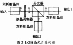
Based on PBS Liquid Crystal Optical Switch Operating Principle Figure 2 is a schematic overview of a 1×2 liquid crystal optical switch. The input birefringent plate controls the polarization of the light to the design direction. Without bias, the laser will pass through the liquid crystal cell and polarization beam splitter with the same polarization direction. By adjusting the voltage of the liquid crystal spatial modulator, the liquid crystal molecules rotate through the polarization of the laser. With a sufficient voltage, the polarization of the laser is rotated to the vertical direction. The polarizing beam splitter now reflects the laser light to another output port.
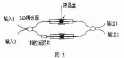
Liquid crystal M-Z direction coupler switch M-Z direction coupler switch, is the basic device of the modern optical communication network. In a single-mode M-Z directional coupler switch, the two interfering arms consist of two similar single-mode fibers. As shown in Figure 3, there are two 3dB couplers at the ends of the fiber. In order to accurately adjust the arm length, an adjustment delay line is also introduced. Another method of adjusting arm length is to apply interference using bundled multi-core fibers and corresponding devices (multi-core connectors and coupling switches). The advantage of this approach is that it is compact, insensitive to ambient pressure and vibration, and the interferometric arm is naturally balanced. However, he needs a 3 dB fully multi-fiber coupling switch. In the following discussion, we assume that the interferometric arms are perfectly balanced (that is, they are exactly equal in length and the propagation constants are exactly the same).
The second very important factor for the M-Z coupler switch of a small weather station is that the photoelectric material can achieve a {0,π} binary phase shift in both arms. In some alternatives, liquid crystals have a higher electro-optic effect than conventional electro-optical materials (eg, GaAs, LiNbO3), thus avoiding long interference lengths and being more attractive. At the same time, they are technically compatible with fiber, although their switching speed is not very fast. However, recent studies have shown that the use of ferroelectric liquid crystal materials (FLC) will increase switching speeds, making this device competitive in network security and maintenance. This solution is usually polarization-sensitive, which is a disadvantage in the field of communications because it is difficult to control the direction of polarization during the transmission of light. However, recent research proposals suggest the use of large tilted FLC materials as half-wave plates. This material is very sensitive to polarization and can achieve a pure binary {0, π} phase delay for output selection.
Guangguangguang has a very important position in the field of agricultural instruments for small weather stations, and is a key component of all-optical networks. Liquid crystal optical switches will occupy very high levels of advantage in the future of optical communications because of their fast response speed and low loss. status.
Hollow Ball,Polyhedral Hollow Ball,Golf Hollow Ball,Plastic Polyhedral Hollow Ball
Wenzhou Xinzhan Valve Ball Co. , Ltd. , https://www.xzfmqt.com