With the further improvement of grid dispatch automation requirements, most of the generating units have been put into the CCS, and are operating in automatic generation control (AGC) mode. CCS is generally designed as two types of "hearth with machine" or "machine with furnace". With the implementation of the new power management model of “Battery Default Assessmentâ€, the coordinated control system of the peaking unit is generally designed as a furnace-based machine, so that the power of the unit can be accurately and timely adjusted to reduce the occurrence of default power. At the same time, in order to increase the economic efficiency of power generation plants, power plants have higher and higher requirements for CCS control indicators. Therefore, a coordinated control system based on hearth furnaces generally adopts a direct energy balance (DEB)-based control strategy to improve control. The system's adaptability to these two requirements.
I. Two Typical Formulas of Direct Energy Balance Control Strategies
The direct energy balance coordination control system generally has two typical formulas (Equation (1), Formula (2)). In the actual design of each control system, only some dynamic compensation functions that improve the performance of the control system are added on this basis.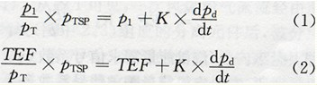
P1 in the formula - speed grade inlet pressure;
PT - pressure before the machine;
PTSP - pre-machine pressure setting;
K - heat release signal coefficient;
Pd - drum pressure;
TEF - total energy flow signal.
The left side of equation (1) represents the steam turbine energy demand (energy command) signal, and the right side represents the boiler heat release (cooking capacity) signal. The traditional understanding is: p1/pT represents the opening signal of the turbine control valve, fast response to the energy demand of the turbine; dPd/dt is the differential signal of the drum pressure, which represents the balance relationship between the boiler heat load and the turbine load. Since the speed-level pressure p1 maintains a good linear relationship with the main steam flow and the turbine load within the unit's 50% to 100% rated load range, and at the same time more accurately represents the turbine energy demand, it is converted to the total energy flow signal TEF ( The enthalpy difference between main steam flow rate or main steam flow rate and feedwater flow rate is substituted for the speed-grade inlet pressure p1 to form equation (2).
Second, the different effects of steam turbine energy demand and boiler heat signal
When the boiler combustion conditions change, due to the difference between the boiler heat load and the steam turbine heat load demand caused by the boiler drum pressure changes, resulting in changes in the boiler heat signal, you can change the boiler combustion rate through the combustion regulator; When the steam pressure is stable, The heat load of the boiler and the steam turbine is basically equal, and the dpd/dt boiler heat signal is equal to the speed-level inlet pressure p1 or the total energy flow signal TEF. If there is a deviation between the pre-machine pressure and the pre-machine pressure setting value, change the boiler combustion rate through the combustion regulator so that the pre-machine pressure gradually approaches the pre-machine pressure setting value; similarly, the pre-machine pressure is equal to the pre-machine pressure setting value. After that, the steam turbine energy demand signal is equal to the speed level inlet pressure p1 or the total energy flow signal TEF. Therefore, the boiler heat signal mainly ensures the balance between the boiler heat load and the turbine heat load, so as to maintain the pressure of the steam drum pressure including the pre-machine pressure; the energy demand signal of the steam turbine mainly adjusts the total heat storage of the boiler to ensure that the pressure before the machine is equal to the setting. value.
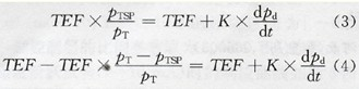
Through the above analysis, formula (2) can be rewritten as formula (3) and formula (4):
Third, the discussion of related issues
3.1 The requirements for the change of the heat storage capacity of the boiler to the boiler are basically the same when the load is different but the pressure deviation is the same
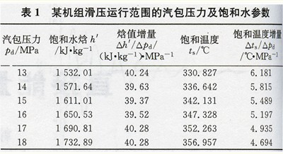
The heat storage capacity of the boiler is mainly related to the effective water volume of the boiler and the effective metal quality of the heating surface. Because the boiler furnace wall heat storage is not large and the heat absorption and heat release are relatively slow, the heat storage can not be considered for the rapidly changing working conditions. The total amount of heat storage reflects the capacity of the boiler against load disturbance, and the total heat storage during the disturbance process. The magnitude of the volume change is only related to the change in the pressure of the steam drum. From the saturated water and steam parameter tables, we can see the ratio of the enthalpy increment and pressure increment of saturated water in a certain range (△h'/Δpd), the ratio of temperature increase of saturated water to the pressure increment (△ts/ △pd) remains basically unchanged. In the normal operation of the unit, the effective water volume of the boiler is basically unchanged, so the total mass of the boiler water is basically unchanged (excluding the influence of density). The total amount of heat released and absorbed by the boiler water and heating surface metal is directly proportional to the change in furnace water temperature and the change in saturation temperature caused by changes in the pressure of the drum, so when the pressure changes in the drum are the same, the total amount of heat stored in the boiler The amount of change is basically the same. The operating data of a 300MW unit is shown in Table 1. The CCS input range is 50% MCR to l00% MCR. The unit adopts constant pressure operation mode (pre-machine pressure 16.8MPa) and constant pressure, sliding pressure and constant pressure operation mode (50% MCR~85). %MCR ~ l00% MCR, pre-machine pressure 13.5MPa ~ 16.8MPa ~ 16.8MPa); CCS assessment indicators for steady state ± 0.2MPa (stable load), dynamic ± 0.5MPa (l0% MCR disturbance, rate 5MW/min) . Therefore, in the normal operating range of the whole unit (50% MCR to l00% MCR), the boiler heat release signal coefficient K can be set as a constant. When the boiler steam pressure changes in the same extent, the total amount of heat storage changes substantially the same, the size of the heat signal depends only on the rate of change of the drum pressure. The change in the total amount of heat stored in the boiler is reflected in the change in pressure in the drum. The increase and decrease in the total amount of heat stored in the boiler leads to a rise and fall in the pressure of the drum.
3.2 When the pressure deviation is the same, the requirement of the energy demand signal of the steam turbine for boiler heat storage varies according to the load.
From equation (4), it can be seen that when the main control system of the steam turbine is in the power operation mode, the amplitude of the turbine energy demand signal generated by the same pressure before the turbine is different under different steam turbine loads (or TEF): the gain for the pre-pressure adjustment In terms of the sliding pressure operation mode, the former is about 1.5 times that of the latter when the 100% load is compared with the 50% load, and the former is twice that of the latter in the constant pressure operation mode.
IV. Alternative understanding of steam turbine energy demand signals
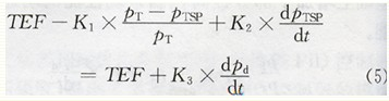
Through the above analysis, it is found that when the same pre-machine pressure or drum pressure deviation is eliminated, the amount of heat storage required by the boiler is basically the same, which is obviously different from the requirement of the energy demand signal of the steam turbine on the boiler heat storage amount, which is also the timing of low load. The reason why the front pressure regulation rate is lower than full load. For an automatic regulating system, it is generally desirable that the gain of the entire regulating system remains relatively constant. In this way, a set of parameters can be used to adapt to the entire operating range, and the quality of the adjustment is basically maintained. Therefore, regardless of the boiler thermal system itself or the automatic regulation system, it is expected that the increment of the turbine energy demand signal generated by the same machine front pressure deviation is substantially the same at different turbine load (TEF). At the same time, in order to meet the greater demand for boiler heat storage change during the sliding pressure operation of the unit, the pre-machine pressure change rate signal and the individual adjustment coefficient are introduced into the steam turbine energy demand signal to increase the flexibility of system adjustment. Based on the above reasons, this paper proposes the following formula for the energy demand signal of steam turbines:
Where K1 - turbine energy demand signal coefficient 1;
K2 - turbine energy demand signal coefficient 2;
K3 - boiler heat release information coefficient.
V. Setting of Turbine Energy Demand Signal
Turbine energy demand signal coefficient l (K1), used to adjust the gain of the pressure deviation before the turbine in the energy demand signal of the turbine, can be adjusted between 50% MCR to l00% MCR or within a larger range according to the actual conditions of the adjustment test. Determine; steam turbine energy demand signal coefficient 2 (K2), used to adjust the adaptability of steam turbine energy demand signal to sliding pressure conditions, can be adjusted for the specific pre-machine pressure setting value after commissioning is completed in constant pressure operation conditions. It is determined in the disturbance test of the pre-machine pressure setting value to ensure the CCS adjustment quality during the sliding pressure operation.
6. Conclusion
It is well known that it is important to optimize the tuning of system parameters for an automatic regulation system. However, it is more important to properly and reasonably design the control strategy of the regulation system. In the CCS test of a 300 MW unit, it was found that using the energy demand signal of the basic structure of the type (5) not only has great flexibility in the tuning of system parameters, but also in the adjustment of the system's rapidity, stability, and adjustment parameters. The adaptability aspects have been greatly improved.
I. Two Typical Formulas of Direct Energy Balance Control Strategies
The direct energy balance coordination control system generally has two typical formulas (Equation (1), Formula (2)). In the actual design of each control system, only some dynamic compensation functions that improve the performance of the control system are added on this basis.
P1 in the formula - speed grade inlet pressure;
PT - pressure before the machine;
PTSP - pre-machine pressure setting;
K - heat release signal coefficient;
Pd - drum pressure;
TEF - total energy flow signal.
The left side of equation (1) represents the steam turbine energy demand (energy command) signal, and the right side represents the boiler heat release (cooking capacity) signal. The traditional understanding is: p1/pT represents the opening signal of the turbine control valve, fast response to the energy demand of the turbine; dPd/dt is the differential signal of the drum pressure, which represents the balance relationship between the boiler heat load and the turbine load. Since the speed-level pressure p1 maintains a good linear relationship with the main steam flow and the turbine load within the unit's 50% to 100% rated load range, and at the same time more accurately represents the turbine energy demand, it is converted to the total energy flow signal TEF ( The enthalpy difference between main steam flow rate or main steam flow rate and feedwater flow rate is substituted for the speed-grade inlet pressure p1 to form equation (2).
Second, the different effects of steam turbine energy demand and boiler heat signal
When the boiler combustion conditions change, due to the difference between the boiler heat load and the steam turbine heat load demand caused by the boiler drum pressure changes, resulting in changes in the boiler heat signal, you can change the boiler combustion rate through the combustion regulator; When the steam pressure is stable, The heat load of the boiler and the steam turbine is basically equal, and the dpd/dt boiler heat signal is equal to the speed-level inlet pressure p1 or the total energy flow signal TEF. If there is a deviation between the pre-machine pressure and the pre-machine pressure setting value, change the boiler combustion rate through the combustion regulator so that the pre-machine pressure gradually approaches the pre-machine pressure setting value; similarly, the pre-machine pressure is equal to the pre-machine pressure setting value. After that, the steam turbine energy demand signal is equal to the speed level inlet pressure p1 or the total energy flow signal TEF. Therefore, the boiler heat signal mainly ensures the balance between the boiler heat load and the turbine heat load, so as to maintain the pressure of the steam drum pressure including the pre-machine pressure; the energy demand signal of the steam turbine mainly adjusts the total heat storage of the boiler to ensure that the pressure before the machine is equal to the setting. value.
Through the above analysis, formula (2) can be rewritten as formula (3) and formula (4):
Third, the discussion of related issues
3.1 The requirements for the change of the heat storage capacity of the boiler to the boiler are basically the same when the load is different but the pressure deviation is the same
The heat storage capacity of the boiler is mainly related to the effective water volume of the boiler and the effective metal quality of the heating surface. Because the boiler furnace wall heat storage is not large and the heat absorption and heat release are relatively slow, the heat storage can not be considered for the rapidly changing working conditions. The total amount of heat storage reflects the capacity of the boiler against load disturbance, and the total heat storage during the disturbance process. The magnitude of the volume change is only related to the change in the pressure of the steam drum. From the saturated water and steam parameter tables, we can see the ratio of the enthalpy increment and pressure increment of saturated water in a certain range (△h'/Δpd), the ratio of temperature increase of saturated water to the pressure increment (△ts/ △pd) remains basically unchanged. In the normal operation of the unit, the effective water volume of the boiler is basically unchanged, so the total mass of the boiler water is basically unchanged (excluding the influence of density). The total amount of heat released and absorbed by the boiler water and heating surface metal is directly proportional to the change in furnace water temperature and the change in saturation temperature caused by changes in the pressure of the drum, so when the pressure changes in the drum are the same, the total amount of heat stored in the boiler The amount of change is basically the same. The operating data of a 300MW unit is shown in Table 1. The CCS input range is 50% MCR to l00% MCR. The unit adopts constant pressure operation mode (pre-machine pressure 16.8MPa) and constant pressure, sliding pressure and constant pressure operation mode (50% MCR~85). %MCR ~ l00% MCR, pre-machine pressure 13.5MPa ~ 16.8MPa ~ 16.8MPa); CCS assessment indicators for steady state ± 0.2MPa (stable load), dynamic ± 0.5MPa (l0% MCR disturbance, rate 5MW/min) . Therefore, in the normal operating range of the whole unit (50% MCR to l00% MCR), the boiler heat release signal coefficient K can be set as a constant. When the boiler steam pressure changes in the same extent, the total amount of heat storage changes substantially the same, the size of the heat signal depends only on the rate of change of the drum pressure. The change in the total amount of heat stored in the boiler is reflected in the change in pressure in the drum. The increase and decrease in the total amount of heat stored in the boiler leads to a rise and fall in the pressure of the drum.
3.2 When the pressure deviation is the same, the requirement of the energy demand signal of the steam turbine for boiler heat storage varies according to the load.
From equation (4), it can be seen that when the main control system of the steam turbine is in the power operation mode, the amplitude of the turbine energy demand signal generated by the same pressure before the turbine is different under different steam turbine loads (or TEF): the gain for the pre-pressure adjustment In terms of the sliding pressure operation mode, the former is about 1.5 times that of the latter when the 100% load is compared with the 50% load, and the former is twice that of the latter in the constant pressure operation mode.
IV. Alternative understanding of steam turbine energy demand signals
Through the above analysis, it is found that when the same pre-machine pressure or drum pressure deviation is eliminated, the amount of heat storage required by the boiler is basically the same, which is obviously different from the requirement of the energy demand signal of the steam turbine on the boiler heat storage amount, which is also the timing of low load. The reason why the front pressure regulation rate is lower than full load. For an automatic regulating system, it is generally desirable that the gain of the entire regulating system remains relatively constant. In this way, a set of parameters can be used to adapt to the entire operating range, and the quality of the adjustment is basically maintained. Therefore, regardless of the boiler thermal system itself or the automatic regulation system, it is expected that the increment of the turbine energy demand signal generated by the same machine front pressure deviation is substantially the same at different turbine load (TEF). At the same time, in order to meet the greater demand for boiler heat storage change during the sliding pressure operation of the unit, the pre-machine pressure change rate signal and the individual adjustment coefficient are introduced into the steam turbine energy demand signal to increase the flexibility of system adjustment. Based on the above reasons, this paper proposes the following formula for the energy demand signal of steam turbines:
Where K1 - turbine energy demand signal coefficient 1;
K2 - turbine energy demand signal coefficient 2;
K3 - boiler heat release information coefficient.
V. Setting of Turbine Energy Demand Signal
Turbine energy demand signal coefficient l (K1), used to adjust the gain of the pressure deviation before the turbine in the energy demand signal of the turbine, can be adjusted between 50% MCR to l00% MCR or within a larger range according to the actual conditions of the adjustment test. Determine; steam turbine energy demand signal coefficient 2 (K2), used to adjust the adaptability of steam turbine energy demand signal to sliding pressure conditions, can be adjusted for the specific pre-machine pressure setting value after commissioning is completed in constant pressure operation conditions. It is determined in the disturbance test of the pre-machine pressure setting value to ensure the CCS adjustment quality during the sliding pressure operation.
6. Conclusion
It is well known that it is important to optimize the tuning of system parameters for an automatic regulation system. However, it is more important to properly and reasonably design the control strategy of the regulation system. In the CCS test of a 300 MW unit, it was found that using the energy demand signal of the basic structure of the type (5) not only has great flexibility in the tuning of system parameters, but also in the adjustment of the system's rapidity, stability, and adjustment parameters. The adaptability aspects have been greatly improved.
This product 200t Cement Silos is adopt sheet-mounted cement silo is connected to the cylinder wall by bolt sealing strips, which is mainly designed and developed for the difficulty of packing and the difficulty in transferring the construction site.China 200 Ton Cement Silo,200T Concrete Cement Silo manufacturer, choose the high quality 200T Cement Silos,200T Bolted Cement Silo, etc.
200 Ton Cement Silo,200T Concrete Cement Silo,200T Cement Silos,200T Bolted Cement Silo
Shandong Zeyu Heavy Industry Science and Technology Co.,Ltd. , https://www.zeyuconcretemachine.com